アナログデバイスのADE7816を用いた電力計のプロトタイプで、最大6チャンネルの測定ができます。 ここには、回路図、基板デザイン、テスト用のプログラムコードが含まれます。
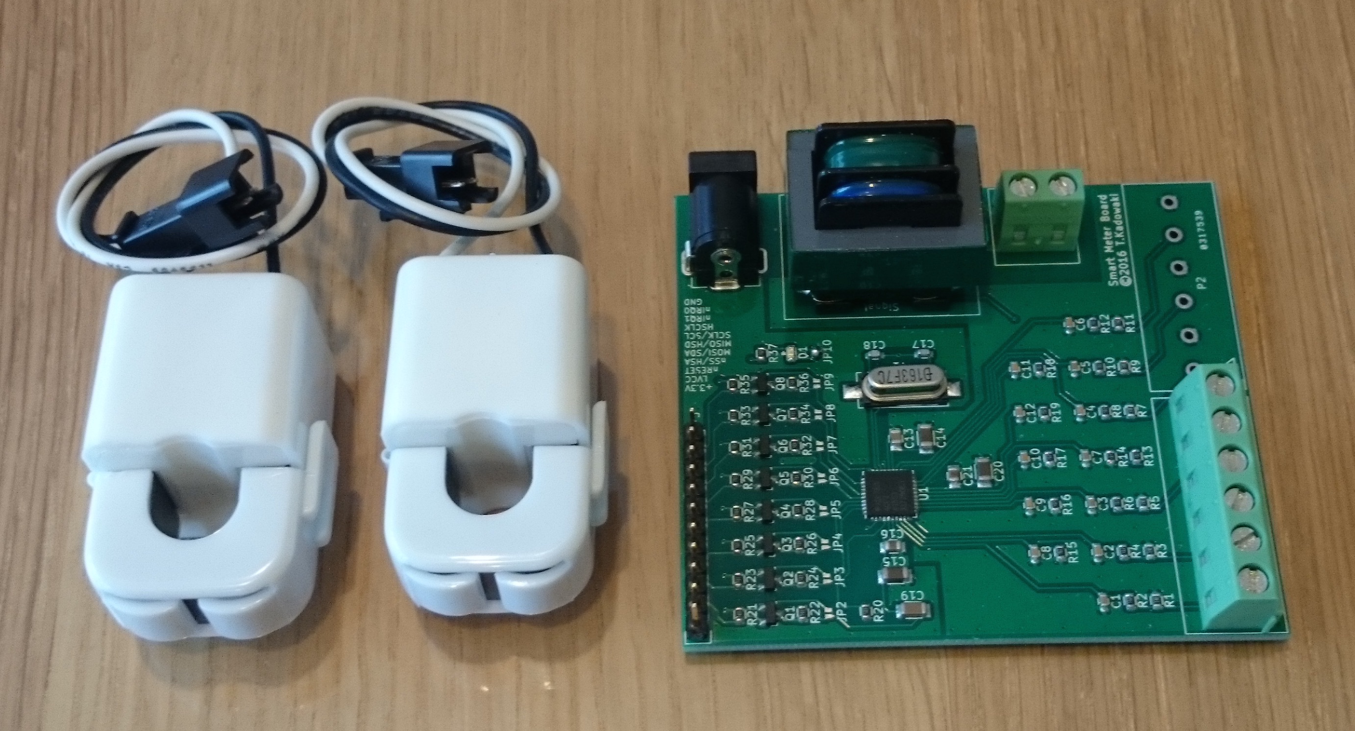
This is a design of smart meter prototype. The board can monitor 6 channels independently utilizing Analog Device ADE7816. This repository includes a set of circuit/breatboard design and example software code.
- KiCad : Smart meter board
- Soft : Javascript examples to control the smart meter board (with Intel Edison)
- FPGA : Raw level data capture function for the smart meter board (Under development)
| Pin | Description |
|---|---|
| 3.3V | 3.3V input for the board |
| LVCC | Reference VCC of cpu board (could be 1.8V) |
| nRESET | Reset ADE7816 (active low) |
| nSS/HSA | Select input for SPI / Port active output for HSDC (active low) |
| MOSI/SDA | Data input for SPI / Data inout for I2C |
| MISO/HSD | Data output for SPI / Data output for HSDC |
| SCLK/SCL | Clock input for SPI / Clock input for I2C |
| HSCLK | Clock output for HSDC |
| nIRQ1 | Interrupt request output (active low) |
| nIRQ0 | Interrupt request output (active low) |
| GND | Ground |
Note: LVCC is designed for a cpu board system with lower voltage such as 1.8V. If you use 3.3V system, you can skip level converters. For such case, use JP2-9 and remove R21-36 & Q1-8.
You can chose I2C or SPI to control ADE7816. HSDC is for capturing raw level data, such as AC voltage and currents. Due to the pin assignment, I2C and HSDC works together. For more details, see the AD7816 manual.
Voltage and current sensing trans used in the board are
- VT2401-A01 http://growwill.co.jp/products/ep/trans/vt/#vt2401-a01
- CTL-10-CLS http://www.u-rd.com/products/CTL-10-CLS.html
If you use another sensors, you may change values of resistors.
CC BY 4.0 Tadashi Kadowaki (tadakado@gmail.com)
Licensed under a Creative Commons Attribution 4.0
https://creativecommons.org/licenses/by/4.0/