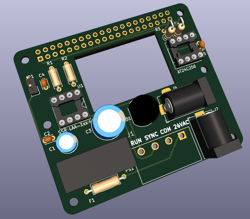
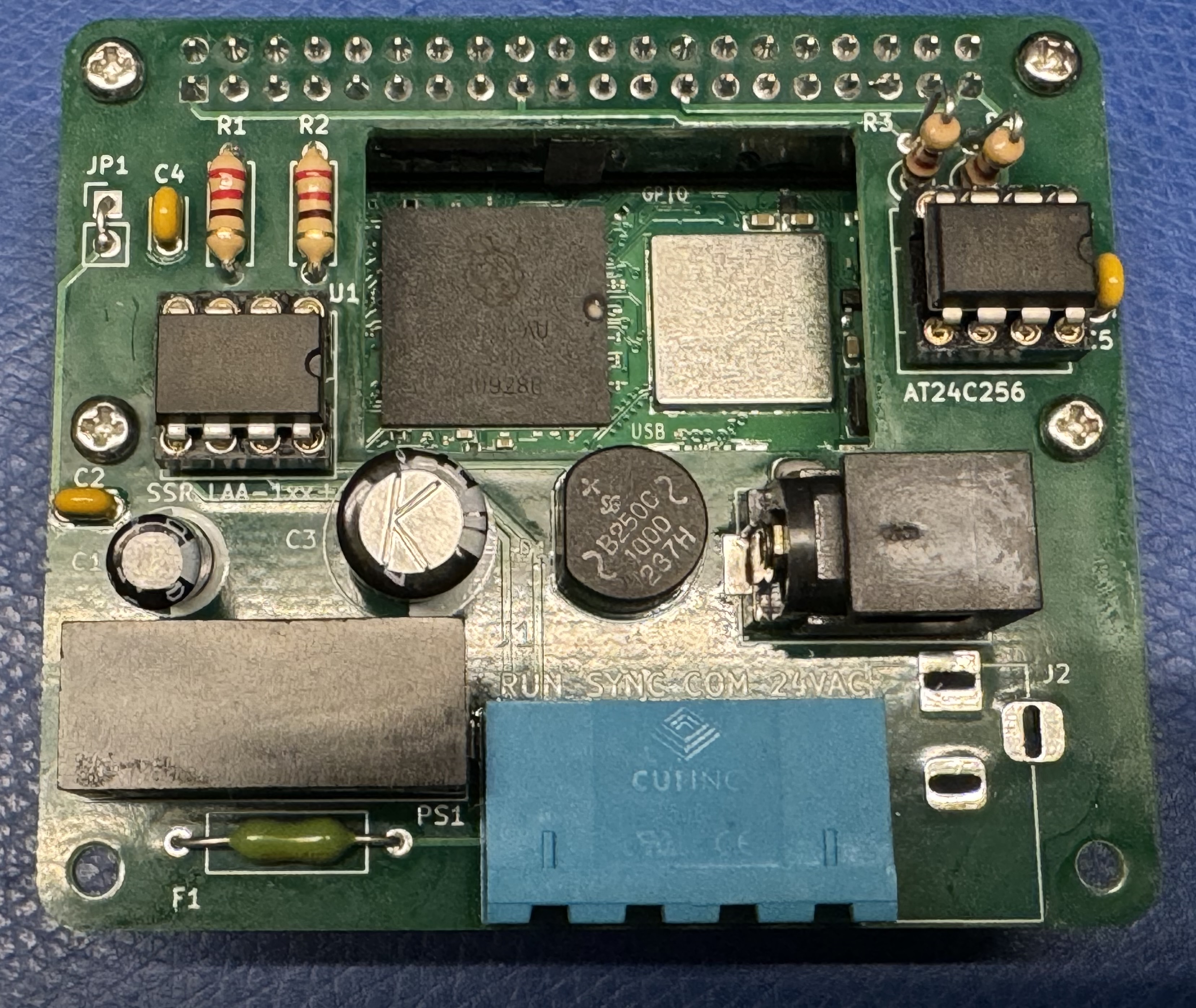
This project is a Raspberry Pi-compatible hat for controlling Simplex Synchronous clocks with a 24VAC motor and 24VAC correction solenoid. This hardware can be used with the master-clock software to implement a synchronous clock controller.
| Pin | Name | Purpose |
| 1 | 24VAC | 24VAC 60Hz Input |
| 2 | 24VAC COM | 24VAC Common (Return) |
| 3 | SYNC | 24VAC Clock Sync Pulse Output |
| 4 | RUN | 24VAC Clock Motor control (optional) |
Note: populate either J2 or J4. J4 is intended to give the hat a smaller footprint when installed inside the clock housing. J2 is intended for use with a full-size Raspberry Pi.
| Pin | Name | Purpose |
| Tip | 24VAC | 24VAC 60Hz Input |
| Ring | 24VAC COM | 24VAC Common (Return) |
Raspberry Pi J3 Signals
| Pin | Raspberry Pi Name | Purpose |
| 1 | 3.3V DC Power | 3.3V DC Power |
| 2, 4 | 5V DC Power | Supplies 5VDC at 1.2A to backpower the RPi. |
| 11 | GPIO17 | SYNC |
| 13 | GPIO27 | RUN |
| 27 | ID_SDA | ID EEPROM I2C Data |
| 28 | ID_SCL | ID EEPROM I2C Clock |
This board contains an AC to DC power supply to power the Raspberry Pi Zero 2 W from the same 24VAC that runs the clock motor. If you do not wish to use this power supply to power the RPi, the following components may be omitted from your build:
| Reference Designator | Component |
| D1 | Bridge rectifier |
| C1, C2, C3, C4 | Capacitors |
| PS1 | SPBW06-5 DC-DC Converter |
| JP1 | Jumper |
When installed, JP1 provides 5VDC to the Raspberry Pi. This hat can supply 5VDC at 1.2A, which is enough for a Raspberry Pi Zero 2W.
Bill of Materials (Interactive BOM)
| Reference | Value | Quantity | DigiKey | Mouser |
| C1 | 10uF / 25V | 1 | ECE-A1EN100UI | ECE-A1EN100UI |
| C2,C4,C5 | 0.1uF | 3 | C315C104M5U5TA7303 | C315C104M5U5TA7303 |
| C3 | 100uF / 100V | 1 | REF1016101M100K | REF1016101M100K |
| D1 | B250C1000G-E4/51 | 1 | B250C1000G-E4/51 | 625-B250C1000G-E4 |
| F1 | 630mA | 1 | F7846CT-ND | 0251.630MAT1L |
| J1 | TBP01R1-508-04BE | 1 | TBP01R1-508-04BE | TBP01R1-508-04BE |
| P1 | TBP01P1-508-04BE | 1 | TBP01P1-508-04BE | TBP01P1-508-04BE |
| J2,J4 | 2.1mm Barrel | 1 | RAPC722BK | RAPC722BK |
| J3 | 2x20 female | 1 | SSQ-120-01-F-D | SSQ-120-01-F-D |
| JP1 | Short with wire. | - | - | - |
| PS1 | SPBW06-05 | 1 | SPBW06F-05 | 709-SPBW06G-05 |
| R1,R2 | 220 ohm | 2 | CFM12JT220R | CFR-25JR-52-220 |
| R3,R4 | 3.9K ohm | 2 | S3.9KHCT-ND | CFR-25JR-52-3K9 |
| U1 | LAA108 | 1 | LAA108 | 849-LAA108 |
| U2 | 24LC256 | 1 | 24LC64-I/P | 24LC64-I/P |
| 8-pin DIP Sockets | 2 | AR 08-HZL-TT | 110-41-308-41-001000 |
The board contains a footprint for a 24C256 or similar serial EEPROM. This EEPROM connects to the Raspberry Pi’s i2c-0 port, and contains configuration data describing the hat.
The i2c-0 port needs to be enabled in /boot/config.txt by manually adding the line:
dtparam=i2c_vc=on
And uncommenting:
dtparam=i2c_arm=on
Reboot the Pi and make sure the EEPROM is detected at address 0x50:
$ i2cdetect -y 0
     0  1  2  3  4  5  6  7  8  9  a  b  c  d  e  f
00:                         -- -- -- -- -- -- -- --
10: -- -- -- -- -- -- -- -- -- -- -- -- -- -- -- --
20: -- -- -- -- -- -- -- -- -- -- -- -- -- -- -- --
30: -- -- -- -- -- -- -- -- -- -- -- -- -- -- -- --
40: -- -- -- -- -- -- -- -- -- -- -- -- -- -- -- --
50: 50 -- -- -- -- -- -- -- -- -- -- -- -- -- -- --
60: -- -- -- -- -- -- -- -- -- -- -- -- -- -- -- --
70: -- -- -- -- -- -- -- --
Use utilities from here: https://github.com/raspberrypi/hats
$ git clone https://github.com/raspberrypi/hats
$ cd hats/eepromutils/
$ make
$ ./eepmake rpi-simplex-clock-hat.txt rpi-simplex-clock-hat.eep
$ sudo ./eepflash.sh -w -f=./rpi-simplex-clock-hat.eep -t=24c64 -d=0
This will attempt to talk to an eeprom at i2c address 0x50. Make sure there is an eeprom at this address.
This script comes with ABSOLUTELY no warranty. Continue only if you know what you are doing.
Do you wish to continue? (yes/no): yes
Writing...
0+1 records in
0+1 records out
149 bytes copied, 0.660765 s, 0.2 kB/s
Closing EEPROM Device.
Done.
Read EEPROM to a file:
sudo ./eepflash.sh -r -t=24c64 -f=readout.eep
After programming the EEPROM and rebooting, the hat information should be available in /proc/device-tree/hat/
3D-printable mounting brackets for the Raspberry Pi Zero 2 W and full-size Raspberry Pi are provided. The Raspberry Pi Zero 2 W can fit inside the clock movement housing.
The software for this project consists of Raspberry Pi OS as well as a Master Clock Daemon which is a Python script that activates the SYNC output at the correct times for hourly and 12-hour corrections.
Install Raspberry Pi OS to MicroSD card using Raspberry Pi Imager. Select Raspberry Pi OS (other) → Raspberry Pi OS (Legacy, 32-bit) Lite.
Change settings to enable WiFi with SSID/Password, set WiFi country, set locale, set username/password.
After booting the Raspberry Pi, ssh in and:
$ sudo apt-get install ntpdate
$ sudo ntpdate time.google.com
$ sudo apt-get update; sudo apt-get upgrade
$ sudo apt-get install git gpiod i2c-tools
$ git clone https://github.com/hharte/master-clock.git
Edit simplex_master_clock.service and change the following line to the correct path for simplex_master_clock.py:
ExecStart=/usr/bin/python3 /home/pi/master-clock/simplex_master_clock.py
$ sudo cp simplex_master_clock.service /etc/systemd/system/
$ sudo systemctl enable simplex_master_clock.service
$ sudo systemctl start simplex_master_clock.service
$ sudo systemctl status simplex_master_clock.service
The Simplex synchronous clocks typically have a 4-pin female Molex MLX connector. These connectors, pins, and tools are available from Amazon:
Connectors: https://www.amazon.com/dp/B07DKZQK5M
Crimper: https://www.amazon.com/gp/product/B0C8MXNWDK
Pin Extractor: DAP-T292328: https://www.amazon.com/dp/B0C4NWRQD4
The clock movements are mounted using pins with spring clips and rubber bushings. These rubber bushings become dried out and brittle with age. If you would like to replace them, the ¼” grommets in this kit work well: 300 Pcs Rubber Grommets Kit.
The synchronous clock controller is designed to support piggybacking with the Uputronics Pi GPS/RTC Expansion Board. When used in conjunction with the GPS Expansion Board, a complete accurate time solution can be realized.
Rev 0 → Rev 1
- Turn SSRs on with logic 1 to GPIO outputs. This is needed so that the SSRs don't become enabled when the GPIO17 and GPIO27 are set to outputs during boot. These GPIOs are pulled low on the RPi.
- Add alternate footprint location (J4) for AC input barrel jack.
- Add additional mounting holes for Raspberry Pi Zero / Zero 2 W.
- Correct pinout for the bridge rectifier D1.

