
"Master the essentials of network configuration and troubleshooting."


- Introduction
- Folder Structure
- Project Requirements - Mandatory Part
- Theoretical Background
- B Mask : 11111111 11111111 00000000 00000000 : 255.255.0.0
- Levels explanation
- Evaluation Process
- Developed Skills
- References
- Support and Contributions
- Author
NetPractice is a technical project focused on developing and refining networking skills through practical exercises and scenarios. This designed to equip students with a profound understanding of network configuration and troubleshooting.
The project covers a wide range of topics, including IP addressing, subnetting, routing, and network troubleshooting. You will have to configure small-scale networks, which requires a solid understanding of how TCP/IP addressing works. The project consists of 10 levels (i.e., 10 exercises) that you will complete and submit to your Git repository. The networks you will work with are not real; instead, they will be available via a training interface that you will access through your web browser. This setup allows for a controlled environment where you can practice and hone your networking skills. The purpose of this project is to solve networking problems and ensure the smooth operation of a network.
.
├── netpractice
│   └── level1.json
│   └── level2.json
│   └── level3.json
│   └── level4.json
│   └── level5.json
│   └── level6.json
│   └── level7.json
│   └── level8.json
│   └── level9.json
│   └── level10.json
├── resources
│   └── net_practice.1.5.tgz
├── LICENSE
└── README.md
First, download the project file from Intra page or directly from this link. Next, extract the files to a folder of your choice. In this folder, open the index.html file. This will launch the interface in your web browser:

The training consists of ten levels, each presenting a non-functioning network diagram. At the top of your window, you will see the goal for each level, outlining the issues you need to resolve to ensure the network operates correctly. You have two main buttons at your disposal:
- Check again: Verifies whether your configuration is correct.
- Get my config: Downloads your current configuration, which is essential for submitting your assignment.
Upon successfully completing a level, a new button will appear, allowing you to proceed to the next level. Before advancing, remember to export your configuration using the Get my config button and save it to your Git repository.
At the bottom of the page, you will find logs that can help you understand why your configuration might be incorrect. To succeed, modify the unshaded fields until your network configuration is correct.
To complete this assignment, it is strongly recommended to understand how addressing works in a network, especially with devices such as routers. Make sure to read about TCP/IP addressing.
You can find my NetPractice logs here. Before diving into the exercises, it's important to familiarize yourself with the theoretical background required for this material.
I know that the theoretical aspects are taken very broadly, but I firmly believe that it is necessary to have a cultural basis on these topics. Feel free to skip some parts or read the whole thing. Enjoy it!
The Internet, a vast network of networks, comprises millions of both public and private networks spanning commercial, academic, and governmental sectors. Individuals typically access the Internet via Internet Service Providers (ISPs), which themselves form networks connecting homes, businesses, and other entities within specific geographic areas. These ISPs also connect to higher-level ISPs to gain broader Internet access, creating a hierarchical structure with a handful of level 1 ISPs at the top and hundreds of thousands of lower-level ISPs at the base. The coverage of ISPs can range from global to local scales. Large content providers, such as Google, often establish their own networks and connect directly to lower-level ISPs to reduce costs and enhance connection speeds for their users.
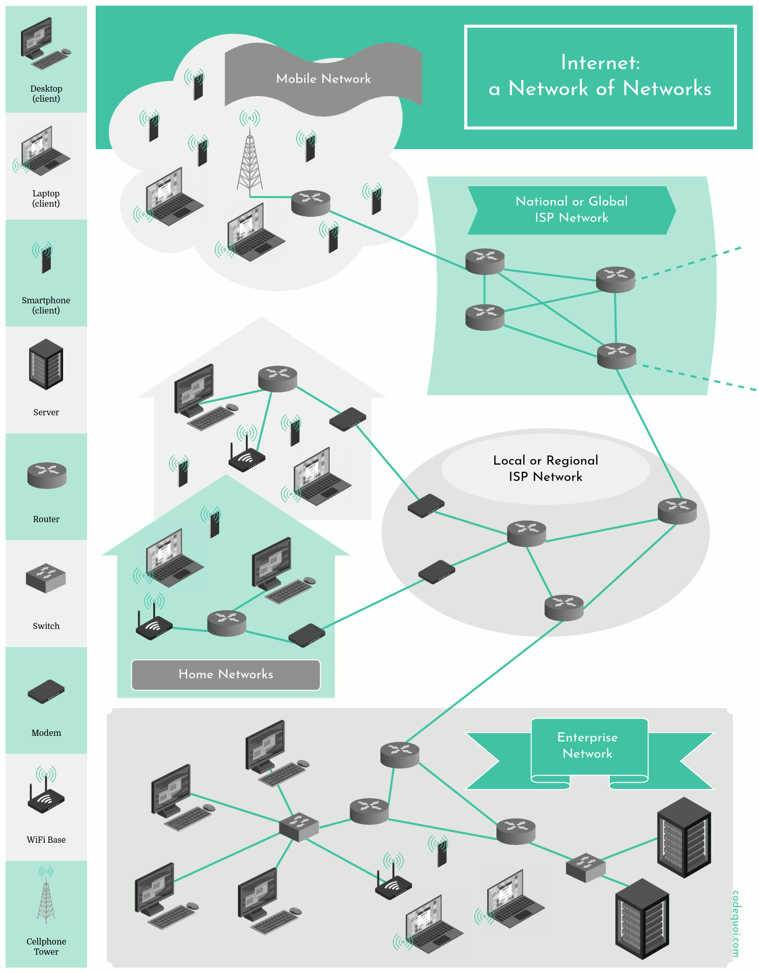
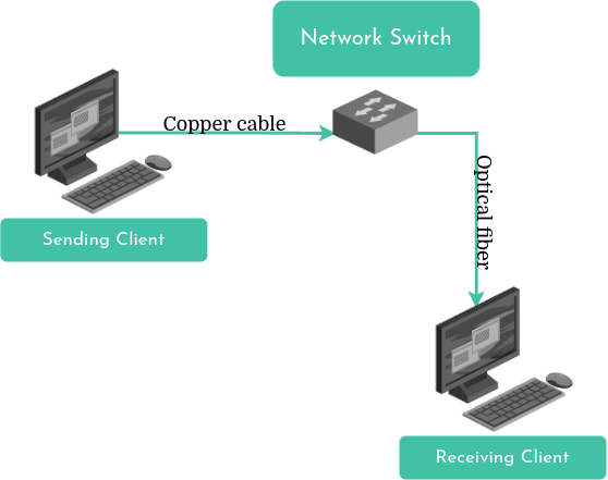
In any network, including the Internet, a host is any connected system. Hosts can be clients like desktops, laptops, smartphones, or servers that store and distribute data. Data sent from one host to another is divided into packets, which are reassembled at the destination.
Hosts connect via various physical media (coaxial cables, copper cables, optical fibers, radio waves) and data packets often pass through switches and routers. Switches manage data traffic within a network, while routers interface between different networks or sub-networks.
Every host, router, and switch is a network node. The sequence of nodes a packet passes through to reach its destination is its route.
Node: In the context of computer networks, a node is any device that can send, receive, or forward information over the network. This includes computers, routers, and switches.
Links (connection between nodes): Nodes are connected to each other through various telecommunication technologies (phisical mediums) including wired (e.g., Ethernet or coaxial cables), optical (e.g., fiber optics), and wireless (e.g., radio waves) methods. The process include these steps: Digitisation, Modulation, Transmission and Demodulation & Decoding. The first step is the digitisation of data. This means converting information, which can be text, images, video or any other type of data, into a sequence of bits (0 and 1). Each bit represents an electrical state (on or off) or a light pulse. Once digitised, the data is modulated on a carrier signal. This carrier signal can be an electromagnetic wave (used in wireless transmissions) or a beam of light (used in fibre optics). Modulation consists of modifying certain characteristics of the carrier signal, such as amplitude, frequency or phase, so that digital data ‘travels over’ it. The modulated signal is then transmitted through the physical medium (cables, optical fibres, radio waves). Upon reception, the signal is demodulated to extract the original digital data. Subsequently, this data is decoded and made comprehensible to the receiving device.
Computer Networks: The connections between nodes form the network's structure, a collection of interconnected devices that share resources and communicate with each other using common communication protocols. Computer networks enable a wide range of applications and services, including access to the World Wide Web, digital video and audio streaming, shared use of application and storage servers, printers, and fax machines, as well as email and instant messaging.
Protocols: Each node in a computer network, whether it's a computer, router, or switch, is identified by a unique network address and may also have a hostname, a memorable label typically assigned during initial setup. These nodes use protocols to send, receive, or forward information over the network. Protocols are sets of rules that dictate how data should be formatted, addressed, transmitted, and received. They also define how to handle transmission errors. Network addresses are used by these protocols, such as the Internet Protocol (IP), to locate and identify nodes. Some common protocols include TCP/IP, HTTP, and FTP.
A network address could be an IP address like 192.168.1.1. This is a unique identifier used by devices to communicate within a network. The Dynamic Host Configuration Protocol(DHCP) server is responsible for assigning IP addresses to devices on a network. When a device connects to the network, it sends a request to the DHCP server, which then assigns an available IP address to the device. The DHCP server keeps track of which IP addresses are currently in use, ensuring that each device on the network gets a unique IP address. If a device disconnects from the network, its IP address is returned to the pool of available addresses and can be reassigned to a different device.
IP (Internet Protocol):: Used to identify devices on a network and to route data packets from one device to another. It is a logical address that can change.This is used to communicate between different networks, over the Internet. When you send an email or browse a website, your device uses its IP address to reach remote servers. An IP address serves as an identifier for a specific network interface, rather than the device itself.
IPv4 is the fourth version of the Internet Protocol. Although the latest version is IPv6, which introduces a new addressing system, IPv4 remains widely used. An IPv4 address is a 32-bit integer, represented as four octets separated by dots. Each octet, a positive number, corresponds to 8 bits. For instance, consider the address 198.42.214.5. Here, 198 is the decimal representation of the first octet, 42 of the second, and so forth. In binary, this address would be:
11000110.00101010.11010110.00000101
Given the 32-bit limitation, the IPv4 address space is finite. The smallest possible address is 0.0.0.0, and the largest is 255.255.255.255:
| Decimal | Binary |
|---|---|
| 0.0.0.0 | 00000000 00000000 00000000 00000000 |
| 255.255.255.255 | 11111111 11111111 11111111 11111111 |
IPv6 expands the IP address length from 32 bits to 128 bits, significantly increasing the number of available addresses. With 128 bits, we can have over 340 sextillion addresses.
IPv6 addresses are represented as hexadecimal numbers. Each address consists of eight groups, each containing 16 bits (2 octets), separated by colons (":").
2001:0db8:0000:85a3:0000:0000:ac1f:8001
We can shorten the notation by removing some non-significant zeros:
2001:db8:0:85a3:0:0:ac1f:8001
MAC (Media Access Control): Used to identify a physical device on the local network. It is a unique and immutable physical address. It is used locally, within the same network, to communicate between devices. For example, when you connect an Ethernet cable to your computer, your network card uses its MAC address to communicate with the network switch.
A hostname is a more human-friendly label for a device on a network. For example, a server might have the hostname webserver1. This hostname can be used to access the server on a local network, provided the network's DNS (Domain Name System) is set up to associate that hostname with the server's IP address.
DNS (Domain Name System): It is like a phone book for the internet. Imagine having to remember the IP address (a long sequence of numbers) for every Web site you want to visit, it would be an impractical task. DNS solves this problem by allowing us to use easy-to-remember names such as www.google.it instead of a complicated IP address.
HTTP (Hypertext Transfer Protocol): is the protocol used for transmitting hypertext over the World Wide Web. It defines how messages are formatted and transmitted, and what actions web servers and browsers should take in response to various commands. For example, when you enter a URL in your browser, this actually sends an HTTP command to the web server directing it to fetch and transmit the requested web page. HTTP uses a stateless request-response model, meaning that each request from a client to a server is processed independently, without any knowledge of the requests that came before it. HTTP is not secure, so it is often replaced by HTTPS, a secure version that uses SSL/TLS protocols to encrypt the communication.
Addressing is the process of assigning a unique identifier, such as an IP address, to each device (node). This allows for precise communication between specific devices. Data is sent across the network in small units called packets. Each packet contains a portion of the data being sent, along with metadata such as the source and destination addresses. Routing is the process of determining the best path for these packets to take from the source to the destination. This is typically handled by devices called routers, which analyze the network's topology and traffic conditions to make this decision. Finally, the Domain Name System (DNS) translates human-friendly domain names (like www.google.com) into the IP addresses that networks use to route traffic. This makes it easier for users to access websites without having to remember complex IP addresses.
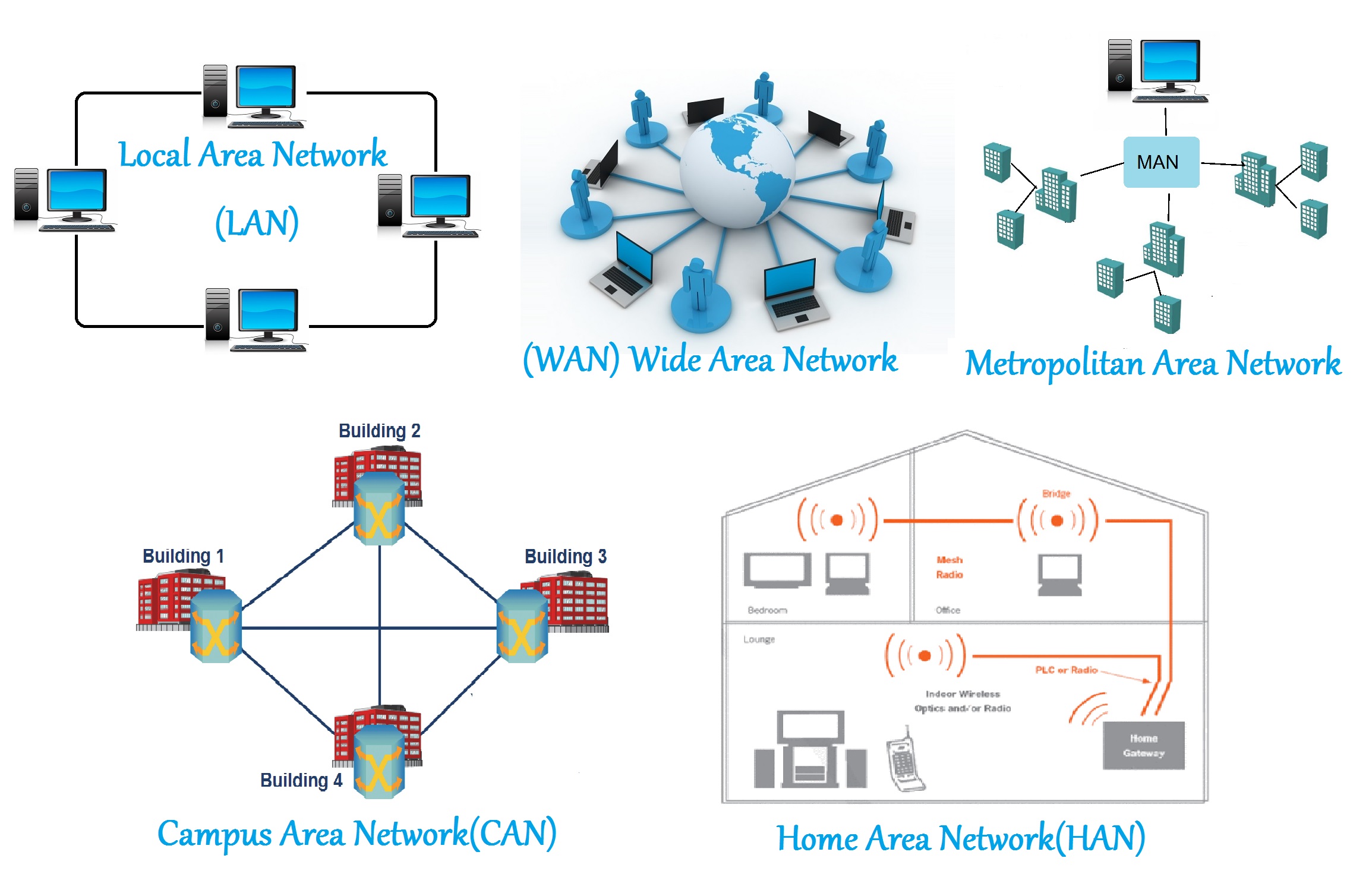
Computer networks can be categorized based on their size and the geographical area they cover. Local Area Networks (LANs) are networks that connect devices over a relatively short distance, such as within a building or campus. Wide Area Networks (WANs) cover larger geographical areas, often spanning cities, countries, or even the globe. Metropolitan Area Networks (MANs) are larger than LANs but smaller than WANs, typically covering a city or suburb. Wireless Local Area Networks (WLANs) are similar to LANs, but use wireless communication methods instead of traditional wired connections. Storage Area Networks (SANs) are networks designed to provide access to consolidated, block-level data storage. Controller Area Networks (CANs) are vehicle bus standards designed to allow microcontrollers and devices to communicate with each other within a vehicle without a host computer. se bit shifting for multiplication,
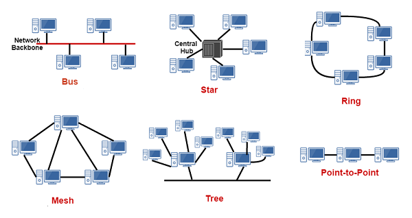
The topology of a network refers to the arrangement of the network nodes and the physical or logical connections between them. Common topologies include the bus, ring, star, mesh, and tree topologies. Each has its own advantages and disadvantages in terms of complexity, robustness, and cost. In general, the more interconnections there are, the more robust the network is; however, this also increases the cost and complexity of installation. The physical layout of the nodes in a network may not necessarily reflect the logical network topology.
Reference models offer a valuable framework for understanding, designing, and troubleshooting computer networks. They promote standardization, modularity, education, and problem-solving.
The Open Systems Interconnection (OSI) model is a reference model from the International Organization for Standardization (ISO) that "provides a common basis for the coordination of standards development for the purpose of systems interconnection." In the OSI reference model, communications between systems are split into seven different abstraction layers: Physical, Data Link, Network, Transport, Session, Presentation, and Application.

Each intermediate layer serves a class of functionality to the layer above it and is served by the layer below it. Classes of functionality are implemented in software development using established communication protocols. Each layer in the OSI model has well-defined functions, and the methods of each layer communicate and interact with those of the layers immediately above and below as appropriate. Although the OSI model is largely theoretical and not all networks strictly adhere to its structure, it provides a useful way to understand and describe how different network protocols interact and co-operate to provide network services.
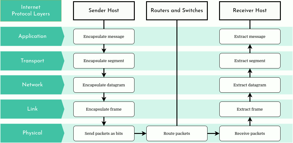
Example:
In this example, we simplify the model by considering only five layers. This approach makes it easier to understand how the model works. We've combined the Presentation, Session, and Transport layers into a single layer, referred to as the Transport layer.
The application layer, the highest layer in the network protocol stack, hosts network applications and their associated protocols. These applications and protocols, which are the very reason for the existence of computer networks, are diverse and continually evolving. The table below showcases only a subset of the most prevalent applications and protocols:
| Application | Protocol(s) |
|---|---|
| Request and transfer Web pages | HTTP, HTTPS |
| File transfer | FTP |
| Email transfer and access | SMTP, IMAP |
| Shell remote access with secure connection | SSH |
| Instant message transfer | IRC, XMPP |
| Clock synchronization to local time | NTP |
| Internet domain name translation into IP | DNS |
| Streaming audio/video | RMTP, HLS, SRT |
| Peer-to-peer file sharing | BitTorrent, eDonkey |
An application-layer protocol facilitates information exchange between applications on different hosts. Packets of the application layer are known as “messages”.
The transport layer of the Internet plays a crucial role in facilitating communication between applications on different hosts. It conveys application-layer messages between application endpoints. The two primary protocols at this layer are TCP and UDP.
TCP is a connection-oriented, reliable protocol. It establishes a connection before data transmission and ensures data is received correctly, resending if necessary. It controls data flow, adjusts transmission speed during network congestion, and breaks down long data streams into smaller segments. TCP is typically used by file transfer, message transfer, web page transfer, and streaming services like YouTube and Netflix.
On the other hand, UDP is a simpler, connection-less protocol. It doesn't regulate traffic or transmission rate and doesn't guarantee message delivery. However, its simplicity is beneficial for quick transmission of small data amounts, such as server-to-client data or situations where data loss is acceptable over retransmission. DNS, voice over IP, and online gaming typically use UDP.
In the transport layer, data packets are referred to as "segments".
The network layer of the Internet is tasked with routing "datagrams" (packets at this layer) from one host to another. The Internet Protocol (IP) is the primary protocol at this layer. It's essential for any host wishing to connect to the Internet, defining the datagram structure and unique IP addresses for each host. Two main versions exist: IPv4 and IPv6, performing similar functions with slight differences.
Other smaller routing protocols, such as RIP, OSPF, IS-IS, and BGP, work alongside IP, primarily determining the datagram's path to its destination. The ICMP protocol communicates information or error messages, like when a service or host is unreachable.
Despite the presence of other protocols, the network layer is often simply referred to as IP, highlighting its central role in holding the Internet together.
The link layer's primary function is to transport a datagram from one network node to the next. It works closely with the network layer, receiving datagrams from it, moving them to the next node, and then passing them back to the network layer.
Link layer protocols are largely dependent on the physical medium between two nodes. These protocols include Ethernet, WiFi, DOCSIS, and PPP. Some ensure reliable packet delivery, while others do not.
A datagram often traverses multiple physical media, requiring different link-layer protocols. For instance, a datagram might be handled by Ethernet on the first link, PPP on the next three, and WiFi on the final link.
At the link layer, data packets are referred to as "frames".
The physical layer, the base layer of the network, is responsible for transmitting individual bits of the link-layer frames from one node to another. The protocols at this layer are intrinsically tied to the physical medium used for transmission and the link-layer protocols above it. For instance, Ethernet employs various physical-layer protocols, each tailored for a specific medium - twisted-pair copper wire, coaxial cable, optic fiber, and so on. Each protocol has a unique method for transmitting a bit across the link.
The TCP/IP (Transmission Control Protocol/Internet Protocol) Model, also known as Internet Protocol suite, is a more practical counterpart to the OSI model. It is the foundation upon which the internet and most commercial networks operate. The TCP/IP model consists of four layers: the Network Interface, Internet, Transport, and Application layers. The Network Interface layer corresponds to the combination of the Physical and Data Link layers in the OSI model. The Internet layer is equivalent to the Network layer in the OSI model, handling IP addressing and routing. The Transport layer is responsible for reliable data transmission, similar to its OSI counterpart. Finally, the Application layer of the TCP/IP model combines the functions of the Session, Presentation, and Application layers in the OSI model. It handles high-level protocols like HTTP and FTP, enabling user applications to interact with the network. It is named after the two most important protocols in the suite: the Transmission Control Protocol (TCP) and the Internet Protocol (IP). TCP/IP provides end-to-end connectivity specifying how data should be packetized, addressed, transmitted, routed, and received at the destination.

https://www.codequoi.com/en/binary-010-uses-of-bit-shifting-and-bitwise-operations/ctual intended message. Headers contain metadata essential for payload delivery, while the payload is extracted and used by an operating system, application software, or higher-layer protocols.


The packets are then sent over the network from the source node to the destination node. Along the way, they may pass through several intermediate nodes, such as routers and switches, which read the packet headers to determine the best path to the destination. This process is known as routing. Once all the packets reach the destination, they are reassembled in the correct order to form the original data. If any packets are lost or damaged during transmission, the error-checking data in the packet headers can be used to detect this and request retransmission of the affected packets. This ensures reliable data transmission over the network. The physical link technologies of packet networks typically limit the size of packets to a certain maximum transmission unit (MTU).
With packets, the bandwidth (the maximum rate of data transfer across a given path) of the transmission medium can be better shared among users than if the network were circuit-switched. When one user is not sending packets, the link can be filled with packets from other users, allowing the cost to be shared with relatively little interference, provided the link is not overused. Often, the route a packet needs to take through a network is not immediately available. In such cases, the packet is queued and waits until a link is free.
Every device connected to internet has at least one network interface, a network card that acts as bridge between the device and the physial medium connected to the rest of the network. A client typically has only one interface since it has only one network connection. A router usually has many, one for each of its network.
A host is any system connected to a network, whether it's a computer, a server, a smartphone, or even a specialized network device. It serves as a node or endpoint in the network, capable of sending and receiving data. A client is a computer, a smartphone, or some other type of connected device. A server is a more powerful machine which stores and distributes content over the Internet.
Each node in a network has a unique network address, which can be used to send data to that node. Nodes can be connected to each other in various ways, forming different network topologies. The way nodes are connected and interact with each other determines many properties of the network, such as its speed, reliability, and resilience to faults.
Like any other type of computer data, a packet is composed of a long series of bits. Each bit in a packet must be moved all the way to its destination (by physical media). Moving a packet’s bits from one physical medium to another is the network switch’s job. Along its route, a packets will no doubt pass through several switches.
Routers are used to route packets, which are not all going to the same destination. Much like a network switch, a router can transfer a packet from one physical medium to another. However, its capabilities extend beyond this. Typically, a router is connected to multiple network segments and possesses the intelligence to determine the optimal path for a packet based on its destination.

Next, we need to comprehend how a router decides the direction to send a packet. This decision-making process utilizes a forwarding table.
A router's primary role is to inspect the headers of incoming packets and determine their destination addresses. This informatihttps://www.codequoi.com/en/binary-010-uses-of-bit-shifting-and-bitwise-operations/
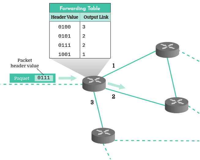
In this scenario, the router inspects the header of the incoming packet and consults its forwarding table to determine that the packet should be routed via interface number 2.
However, consider the fact that there are approximately 4 billion 32-bit IPv4 addresses. A router with a forwarding table containing entries for all 4 billion addresses would be highly inefficient and slow, even with an optimized routing algorithm. Wouldn't it be more efficient to determine the packet's destination by reading just the initial bits of the address? Precisely! This is one of the benefits offered by the concept of subnetworks.
An IP address is divided into two parts: the network prefix and the host identifier. The network prefix identifies the subnetwork to which the device belongs, while the host identifier specifies the particular device within that subnetwork. When a router receives a packet, it typically only needs to examine the network prefix to determine the packet's destination. To distinguish between the network prefix and the host identifier, a router uses a subnet mask. But how many bits does the network prefix comprise? The answer might be more complex than you think…
Internet is a network made of many subnetworks. IP addresses are assigned by range depending on the size of the subnetwork. Originally, address ranges were categorized into several classes: A for the largest networks, B for medium-sized networks and C for the smallest networks. So the 8, 16 or 24 first bits of the IPv4 address represented the subnetwork, and the following bits identified the host within that subnet.
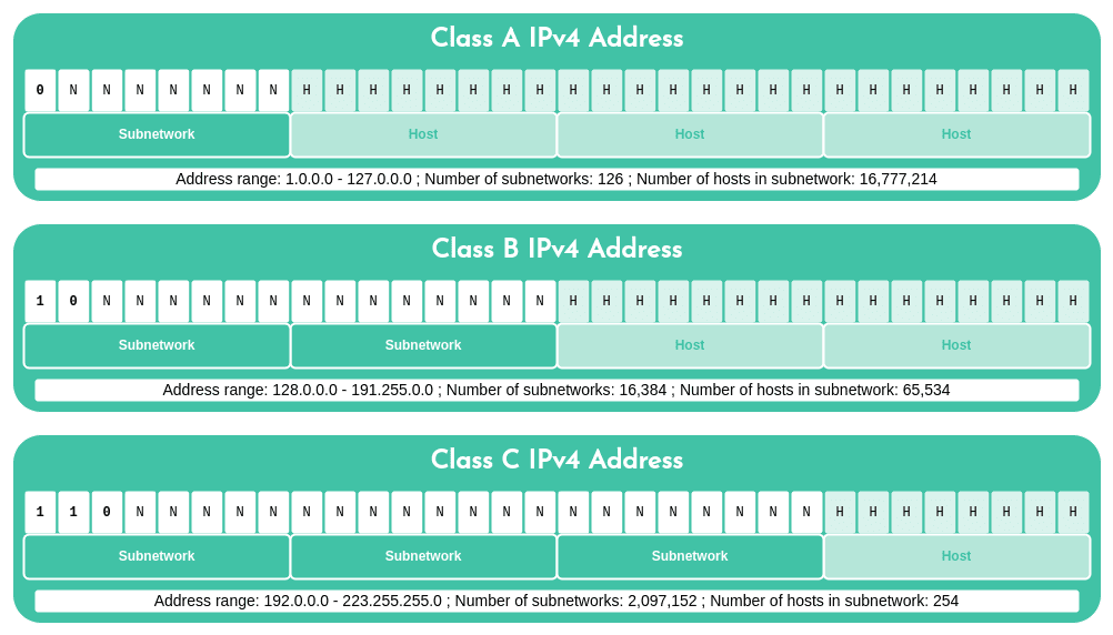
To identify the subnetwork bits, we first needed to determine the address class. If the first bit was 0, it was a class A network; if the first two bits were 1 and 0, it was class B; if the first three were 110, it was class C. We could then apply the appropriate subnet mask and perform a bitwise AND operation to isolate the subnetwork.
For example, consider the IP address 167.45.198.2:
IP : 10100111 00101101 11000110 00000010 : 167.45.198.2 B Mask : 11111111 11111111 00000000 00000000 : 255.255.0.0 Bitwise & : 10100111 00101101 00000000 00000000 : 167.45.0.0
However, by the 1990s, the rigid structure of having 1, 2, or 3 octets represent the subnet in an address was proving inadequate for the growing number of small to medium-sized networks. A class C subnet could only support 254 hosts - too few for most organizations. Conversely, a class B subnet, supporting up to 65,354 hosts, was often excessive. For instance, an organization needing to connect 2,000 hosts would receive a class B subnet, resulting in a wastage of around 63,000 addresses that couldn't be used elsewhere.
As a result, the classful IPv4 addressing method was replaced with a more flexible classless system, known as CIDR (Classless Inter-Domain Routing), which is still in use today.
In order to isolate the bits representing the subnetwork, it was necessary to first identify its class. If the first bit was 0, the address belonged to a class A network; if the first two bits were 1 and 0, the address was class B; if the first three were 110, then it belonged to class C. Then, we could apply the appropriate subnet mask as well as the bitwise AND operation to identify the subnetwork.
IP : 10100111 00101101 11000110 00000010 : 167.45.198.2 B Mask : 11111111 11111111 00000000 00000000 : 255.255.0.0
Bitwise & : 10100111 00101101 00000000 00000000 : 167.45.0.0 (result of bitwise AND)
However, in the 1990s, having 1, 2 or 3 octets representing the subnet in an address proved to be too rigid of a system to support the growing number of small to medium organization networks. A class C subnet could only accommodate 254 hosts: too few for most organizations. But a class B subnet, which could support up to 65,354 hosts, was much too big! Yet with this system, an organization wishing to connect 2,000 hosts would get a class B subnet. Cases like this represented a loss of 63,000 addresses that could not be used by any other organizations.
Therefore, this classful IPv4 addressing method was soon abandoned in favor of a classless addressing system which is still in use today : CIDR.
Classless Inter-Domain Routing ( CIDR) generalized the notion of subnetworks by making it more flexible. In this system, the subnet part of the address is not fixed as in the class method above. CIDR subnet masks can be of varying lengths, which allows for a much more efficient use of IP address space.
Since the subnet mask can no longer be deduced from the IP address itself, CIDR introduced a new notation to indicate the number of bits representing the subnetwork. The four-octet IPv4 address may be followed by a slash, and then the number of subnetwork bits. For example, 128.42.42.201/28 indicates that the 28 first bits of the address represent the subnetwork:
IP : 10000000 00101010 00101010 11001001 : 128.42.42.201 /28 Mask : 11111111 11111111 11111111 11110000 : 255.255.255.240 Bitwise & : 10000000 00101010 00101010 11000000 : 128.42.42.192
The formula to determine the number of possible addresses within a subnetwork is 2address length - mask. This means that there are 232-28 = 24 = 16 possible IPv4 addresses in this 28-bit subnet range:
IP : 10000000 00101010 00101010 11001001 : 128.42.42.201 /28 Mask : 11111111 11111111 11111111 11110000 : 255.255.255.240 IP min : 10000000 00101010 00101010 11000000 : 128.42.42.192 IP max : 10000000 00101010 00101010 11001111 : 128.42.42.207
In this way, an Internet Service Provider may receive a /19 bloc, meaning 232-19 = 213 = 8,192 IPv4 addresses. It can then break this block down into subnetworks of varying sizes depending on its client’s needs. For example, for one small organization requiring 200 connected hosts, it could provide a /24 subnet (2^(32-24) = 2^(8) = 256 addresses). To a larger company requiring 2,000 hosts, it could allocate another /20 subnet (232-21 = 211 = 2,048 addresses).
But how do these CIDR subnet masks work to help route a packet to its destination, in practice? To understand this, let’s map out a small fictitious part of Internet.
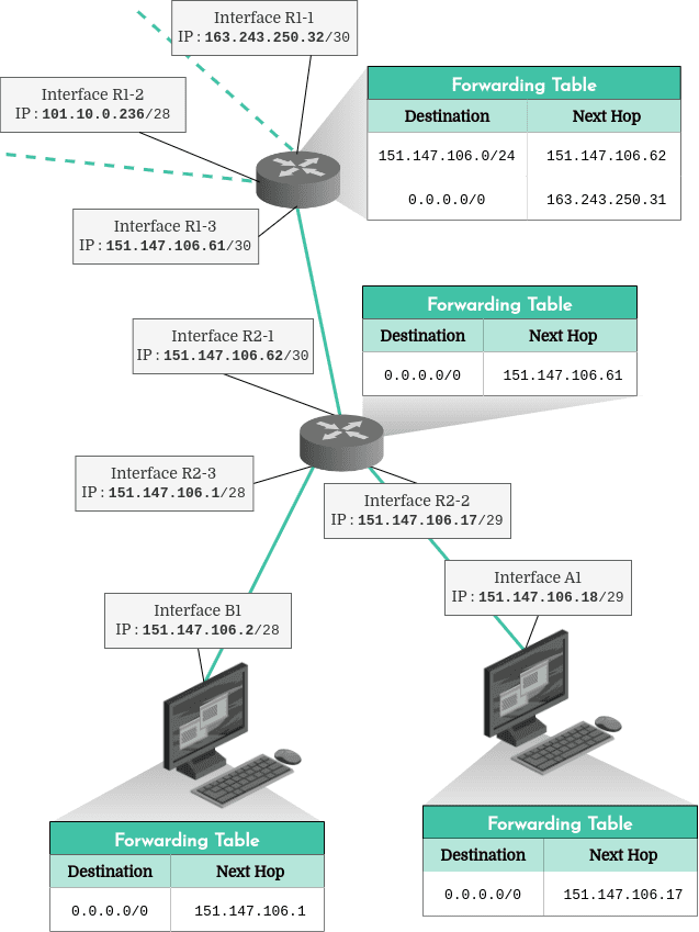
The first thing we might notice here is that each client and router has a forwarding table which informs it where to send packets. The router at the top of the diagram has two entries in its forwarding table. The first entry indicates that all incoming packets with addresses starting with the first 24 bits being 151.147.106.x must be sent to the second router’s interface with the address 151.147.106.62. That’s the “next hop” on the route to their destination. The second entry in this same forwarding table indicates that by default, all packets should be sent to 163.243.250.31 (another router connected to the R1-1 interface which doesn’t appear on this diagram), whatever their destination ( 0.0.0.0/0).
There are three distinct subnets in this diagram:
The 30-bit subnet 151.147.106.60, which contains the two routers’ interfaces, R1-3 ( 151.147.106.61) and R2-1 ( 151.147.106.62). A 28-bit subnet, 151.147.106.0, containing the router’s R2-3 interface ( 151.147.106.1) and the client’s B1 interface ( 151.147.106.2). The addresses inside this subnetwork must be between 151.147.106.1 and 151.147.106.14. And a 29-bit subnet, 151.147.106.16, which contains the router’s R2-2 interface ( 151.147.106.17) and the client’s A1 interface ( 151.147.106.18). The interfaces inside this subnet must have addresses between 151.147.106.16 and 151.147.106.22. Of course, subnets should not overlap. For example, we couldn’t assign the address 151.147.106.3 to the R2-2 interface, since that address is part of the R2-3 interface’s subnet.
Reserved IPv4 Addresses About 600 million IPv4 addresses are reserved for specific uses and cannot be assigned. These addresses are used, among other things, for multicast traffic, to maintain router tables, to translate IPv4 to IPv6, or to provide unrestricted address space for private networks.
Address Blocks Range of Addresses Number of Addresses Use 0.0.0.0/8 0.0.0.0 – 0.255.255.255 16 777 216 Software 10.0.0.0/8 10.0.0.0 – 10.255.255.255 16 777 216 Private network: local communications 100.64.0.0/10 100.64.0.0 – 100.127.255.255 4 194 304 Private network: ISP communications 127.0.0.0/8 127.0.0.0 – 127.255.255.255 16 777 216 Host: loopback addresses for localhost 169.254.0.0/16 169.254.0.0 – 169.254.255.255 65 536 Subnet: local communications between two hosts on a single link 172.16.0.0/12 172.16.0.0 – 172.31.255.255 1 048 576 Private network: local communications 192.0.0.0/24 192.0.0.0 – 192.0.0.255 256 Private network: IETF protocol assignments 192.0.2.0/24 192.0.2.0 – 192.0.2.255 256 Documentation: TEST-NET-1 192.88.99.0/24 192.88.99.0 – 192.88.99.255 256 Reserved: 6to4 relay 192.168.0.0/16 192.168.0.0 – 192.168.255.255 65 536 Private network: local communications 198.18.0.0/15 198.18.0.0 – 198.19.255.255 131 072 Private network: bench-marking between two connected subnets 198.51.100.0/24 198.51.100.0 – 198.51.100.255 256 Documentation: TEST-NET-2 203.0.113.0/24 203.0.113.0 – 203.0.113.255 256 Documentation: TEST-NET-3 224.0.0.0/4 224.0.0.0 – 239.255.255.255 268 435 456 Reserved: IPv4 multicast 233.252.0.0/24 233.252.0.0 – 233.252.0.255 256 Documentation: MCAST-TEST-NET 240.0.0.0/4 240.0.0.0 – 255.255.255.254 268 435 455 Reserved: for future use 255.255.255.255/32 255.255.255.255 1 Subnet: limited broadcast destination address As we can see in this table, come addresses are reserved for technical purposes (testing, documentation, protocol assignments). But what does “private network” mean, exactly?
Public vs Private Addresses A public address is assigned to a router by an Internet Service Provider, and allows communications over the Internet. So with a public address, one can send and receive packets from anywhere on the Internet.
A private address is assigned by a router to each device connected to it. This private address allows communication within the same subnetwork, for example between devices connected to the same WiFi network. Of course, a device cannot use its private address to send or receive packets from outside its network. This private address system saves IPv4 address space since several devices may have the same private address as long as they aren’t on the same subnet.
Network Addresses and Broadcast Addresses Network and broadcast addresses do not appear on the list of reserved addresses above. However, they should generally not be used either.
Each subnetwork address range starts with the address of the network itself. For example, the address 130.200.189.45/24 is part of an address block starting at 130.200.189.0/24. This address is therefore considered the network address and cannot be assigned to an interface.
The same goes for the last address in a block. If we go back to the previous example, the last address in that block is 130.200.189.255/24. This address is called the broadcast address because a packet sent to it is transferred to all interfaces in the subnetwork. For this reason, broadcast addresses cannot be assigned to a device interface either.
Curbing the IPv4 Address Shortage A 32-bit length means that there are around 4 billion IPv4 addresses. That’s a lot! Yet it isn’t enough for all devices connected to this global network. 4 billion, that’s only half of the human population. And more and more citizens of developing countries are using the Internet. Further, a growing number of objects are now also connected to the Internet: watches, cars, smart cities, seismic monitoring or home security systems… In short, the Internet of Things.
Foreseeing increasing Internet usage in the 1990s, the Internet Engineering Task Force focused on a successor to IPv4, which could offer many more addresses…
CIDR subnet masks and notations also apply to IPv6 addresses.
Since it is inconceivable to turn off the entire Internet for the time it would take to update all hosts and routers to the new IP version, IPv6 is progressively deployed. IPv6 is backward-compatible with IPv4, but the opposite is not necessarily true. Some routers and hosts are incapable of running IPv6. Until they can be replaced, an IPv6 packet that must travel through an incompatible router can temporarily disguise itself as IPv4 before being restored to IPv6 further along its route, if possible.
Modem: A modem (short for modulator-demodulator) is a device that converts data between digital formats used by computers and analog formats used by older telephone lines or radio signals. In a home network, the modem connects to the internet service provider's network, allowing devices in the home to access the internet.
Router: A router is a device that forwards data packets between computer networks, creating an overlay internetwork. Routers perform the traffic directing functions on the internet; data sent throughttps://www.codequoi.com/en/binary-010-uses-of-bit-shifting-and-bitwise-operations/h the internet, such as a web page or email, is in the form of data packets. A packet is typically forwarded from one router to another through the networks that constitute the internet work until it reaches its destination node.
Bridges: A network bridge is a computer networking device that creates a single aggregate network from multiple communication networks or network segments. This function is called network bridging. Bridging is distinct from routing, which allows multiple different networks to communicate independently while remaining separate.
Firewall: A firewall is a network security device that monitors incoming and outgoing network traffic and decides whether to allow or block specific traffic based on a defined set of security rules. Firewalls have been a first line of defense in network security for over 25 years. They establish a barrier between secured and controlled internal networks that can be trusted and untrusted outside networks, such as the internet.
Network Interfaces: A network interface is the point of interconnection between a computer and a private or public network. A network interface is generally a network interface card (NIC) but does not have to have a physical form. Instead, the network interface can exist in software or can be a combination of hardware and software.
Repeaters: A repeater is an electronic device that receives a signal and retransmits it at a higher level or higher power, or onto the other side of an obstruction, so that the signal can cover longer distances. In a wired network, a repeater can receive a signal on an electromagnetic or optical transmission medium, amplify it and retransmit it. Repeaters overcome the attenuation caused by free-space electromagnetic-field divergence or cable loss.
Hubs: A network hub is a node that broadcasts data to every computer or Ethernet-based device connected to it. A hub is less sophisticated than a switch, the latter of which can isolate data transmissions to specific devices. The hub does not manage any of the traffic that comes through it; any packet of data entering any port is rebroadcast out on every other port. In a hub, a frame is passed along or "broadcast" to every one of its ports. It does not matter that the frame is only destined for one port. The hub has no way of distinguishing which port a frame should be sent to.
Spoiler Alert: Before viewing the solutions, try to solve them on your own.
LEVEL 1
Submit your assignment in your Git repository as usual. Only the work inside your repository will be evaluated during the defense. Double-check the names of your files to ensure they are correct.
Since there are 10 levels in the training interface, you need to submit 10 files in your repository (one file per level). Place them at the root of your repository. Make sure to enter your login in the training interface and export a file per level using the Get my config button. It is crucial that you enter your login in the interface.
During the defense, you will be required to successfully complete 3 random levels as specified on the training platform. You will have a limited time to do so. The use of external tools is not allowed during your evaluation. However, the use of a simple calculator such as bc is tolerated but will be the limit.
bc is a command-line calculator that supports arbitrary precision arithmetic. It is commonly used in Unix-like operating systems, including Linux. bc stands for "basic calculator" and can handle complex mathematical expressions, including floating-point calculations, making it a useful tool for quick computations directly from the terminal.
# Start bc in interactive mode
bc

# Perform a calculation
scale=2
5 / 3

# Output: 1.66


-
CodeQuoi: Internet Layered Network Architecture - A comprehensive guide to the architecture of Internet networks, explaining the different layers and their functions.
-
CodeQuoi: Binary 001 - Counting & Calculating Like a Computer - This resource provides a deep dive into the binary number system, which is fundamental to computer operations. It explains how computers use binary for counting and calculations, making it a valuable resource for understanding low-level computer operations.
-
CodeQuoi: IPv4 Addresses, Routing, and Subnet Masks - Detailed explanation of IPv4 addressing, routing, and subnet masks, key concepts in network communication.
-
Wikipedia: Computer Network - An overview of computer networks, including their history, types, and key principles.
-
Wikipedia: Datagram - Detailed explanation of datagrams, basic units of data transfer in packet-switched networks.
-
Wikipedia: Packet Switching - Detailed article on packet switching, the method used to send data across networks.
-
Wikipedia: OSI Model - Comprehensive article on the OSI Model, a conceptual framework used to understand network interactions.
-
BMC Blog: Understanding the OSI Model - A blog post that breaks down the seven layers of the OSI Model and their functions.
-
Wikipedia: Internet Protocol Suite - Detailed article on the Internet Protocol Suite, also known as TCP/IP, the set of protocols used for the Internet.
-
Wikipedia: IP Address - Comprehensive article on IP addresses, unique identifiers for devices on a network.
-
Netpractice on Medium - A Medium article discussing the concept of network practices.
-
New Subnetting on Medium - A Medium article explaining the concept of subnetting in networking.
-
42bangkok-netpractice on GitHub - A GitHub repository.
-
NetPractice on GitHub - Another GitHub repository.
-
42-net-practice on GitHub - Another GitHub repository.
-
Net_Practice on GitHub - Another GitHub repository.
If you find this repository helpful, please consider starring it to show your support. Your support is greatly appreciated!


