Home
Please note, this wiki is no longer maintained, you can find the latest documentation on readthedocs.
VID_20230119_175559892.mp4
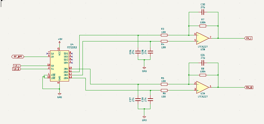
Pi Pico Rx is a minimal SDR receiver based around the Raspberry Pi Pico. The design uses a "Tayloe" Quadrature Sampling Detector (QSD) popularised by Dan Tayloe. And used in many HF SDR radio designs. This simple, design allows a high-quality mixer to be implemented using an inexpensive analogue switch.
A quadrature oscillator is generated using the PIO feature of the RP2040. This eliminates the need to use an external programmable oscillator. Without overclocking the device this supports frequencies up to about 30MHz, conveniently covering the LW, MW and SW bands.
The IQ output from the QSD is amplified using a high-speed, low-noise op-amp. The I and Q channels are sampled by the built-in ADC which provides 250kHz of bandwidth. The dual-core ARM Cortex M0 processor implements the Digital Signal Processing algorithms, demodulating AM, FM, SSB and CW to produce an audio output.
Audio output is provided using a PWM followed by a low-pass filter. At first, I used an LM386 audio amplifier, but later found that with a suitable current limiting resistor the IO pin could easily drive a pair of headphones or even a small speaker directly.
A cobbled-together prototype proves that it is possible to build an HF SDR receiver using a Pi Pico, an analogue switch, an op-amp and a handful of discrete components.
This isn't a new idea by any means, there are loads of SDR designs out there. Some use a PC soundcard, others use a built-in CPU for the SDR. The uSDX project even does the DSP processing using an 8-bit micro! I have put a list of links to some of the other projects that have inspired me. Each of these projects introduces new ideas and innovations. I hope that the Pi Pico Rx has introduced some of its own evolutionary developments that might inspire others with their designs.
- softrock SDR
- QRP Labs
- mcHF
- elecraft KX3
- usdx
- (tr)uSDX
- uSDR-pico
- compact-si5351-based-sdr
- qex
- Teensy-Convolutional SDR
Continuing in the spirit of knowledge sharing, I have attempted to describe the finer details of the hardware and software in this wiki, starting here with an overview of the new features introduced by the Pi Pico Rx that I haven't seen before in other designs.
One of the challenges I faced was sampling IQ signals using an ADC that is only capable of sampling one channel at a time. It can be configured in a round-robin mode that samples I and Q alternately. I had worried that this might create a phase imbalance between the I and Q channels. I needn't have worried, it turns out that there is a simple way to recover a complex signal with 250kHz bandwidth by sampling I and Q alternately at 500kSample/s.
The trick is to low pass filter the I and Q data leaving 250kHz of bandwidth from -125kHz to 125kHz. The QSD detector itself forms a low-pass filter, so this can easily be achieved by selecting suitable capacitor values in the op-amp. The ADC is configured to sample I and Q alternately (starting with I). In the software, the "missing" values can be replaced by zeros.
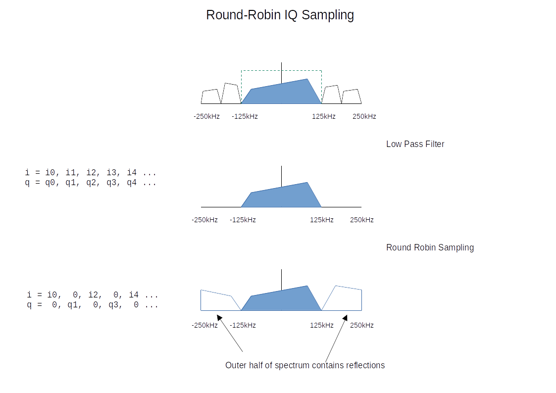
This results in a complex signal with a sampling rate of 500KS/s. The central half of the spectrum from -125kHz to 125kHz contains the spectrum we want. The outer half of the spectrum from -250kHz to -125kHz and 125kHz to 250kHz contains reflections of the central half. To recover the original spectrum, we simply need to low-pass filter the signal so that we retain the central section. We could then reduce the sample rate to 250kHz. In our application, we filter out only a very small section of the spectrum containing the signal of interest, we don't need to take any additional steps to remove the reflections.
To understand why this works, it helps to think about how we could have converted the signal into a real (rather than complex IQ) signal and sampled it using a single-channel ADC. This is one of the approaches I had originally considered taking. I only realised that there was an easier way once I worked the problem through. This was my thought process.
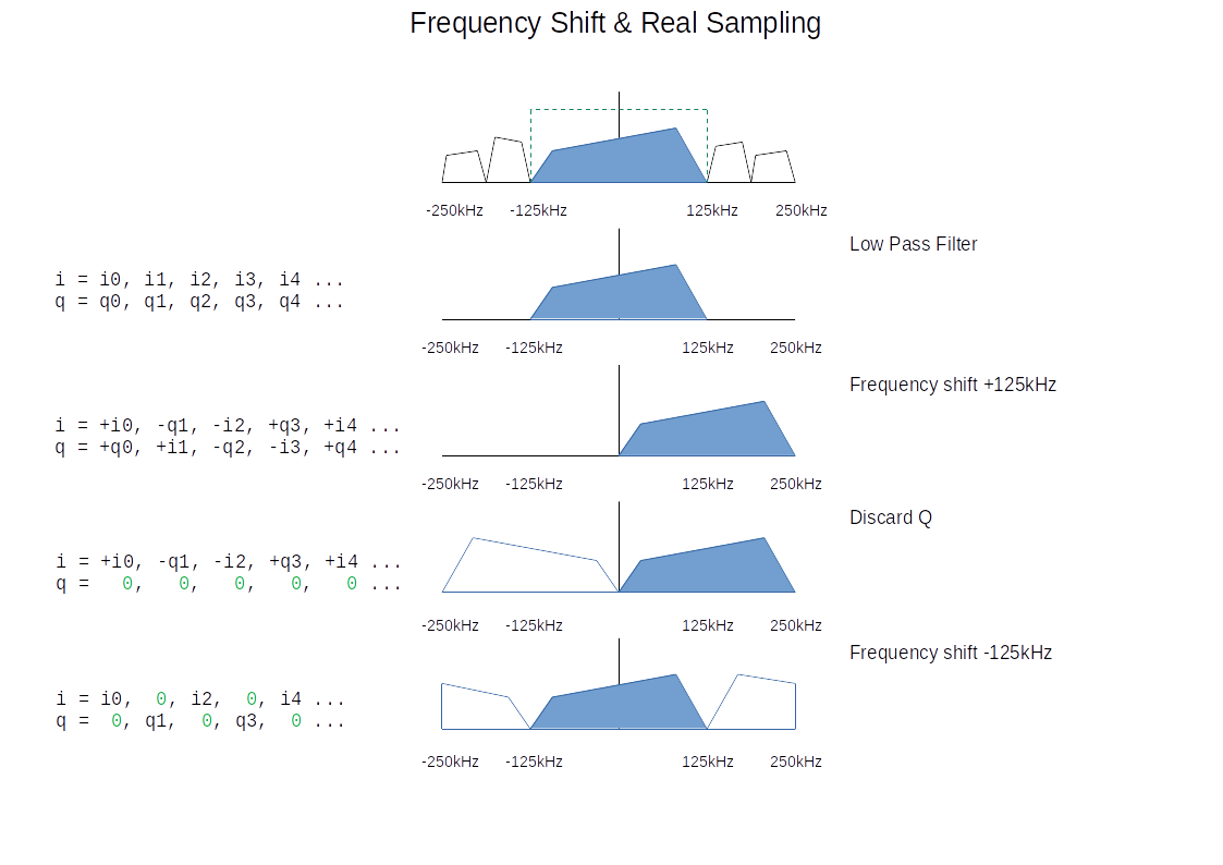
To satisfy Nyquist, we need to filter the complex data so that all our signals sit between -125kHz and 125kHz. We could then shift the data up by 125kHz so that our signals are between 0 and 250kHz. The frequency shift is 1/4 of the 500KSample/second sample rate. A frequency shift by Fs/4 can be implemented by rotating the signal by 1/4 turn in each sample. This doesn't need any multiplication, only negation.
Since our signal now only contains positive frequencies, the imaginary (Q) part of the signal doesn't contain any useful information and we can throw it away. A signal containing only real (I) values has a symmetrical spectrum, discarding the imaginary samples introduces negative frequency reflections of the positive frequency signals.
The real signal can now be sampled with a single-channel ADC at 500kSamples/s. The frequency shift could have been implemented in hardware using a simple mixer, but we only need I and Q samples alternately, so we could use a round-robin ADC to capture the alternate I and Q samples and implement the mixer in software, negating I and Q when necessary.
Once we have the real signal in the software, we might like to convert the real signal back to a complex one. We could use a Hilbert transform, this would filter out the negative frequencies leaving a complex signal with an asymmetrical spectrum containing only positive frequencies from 0 to 250kHz.
Another approach would be to shift the frequencies down by 125kHz leaving the original spectrum from -125kHz to 125kHz, now with reflections in the outer half of the spectrum. These could be removed with a low-pass filter. We can take the same approach to the Fs/4 frequency shift, this time rotating 1/4 turn each sample in the opposite direction.
Inspecting the resulting samples, we can see that the downwards frequency shift has cancelled out the negations we performed during the upwards frequency shift, leaving us with the alternating I/Q samples we originally captured.
Conveniently, it turns out, the alternating IQ samples captured from the round-robin ADC were the only samples we needed to fully capture the central half of the frequency spectrum. The "missing" samples only contributed to the outer part of the spectrum that we had already filtered out.
The pi pico is based on the RP2040 microcontroller. The PIO is a novel feature of the RP2040. Programmable State Machines (like small microprocessors) can be configured to offload IO functions from the software. It is fairly simple to configure a PIO state machine to output a quadrature oscillator on 2 IO pins. Once configured the Oscillator runs autonomously without software intervention, not placing any further load on the CPU.
The PIO program is remarkably simple:
    .program nco
	set pins, 0
	set pins, 1      ; Drive pin low
	set pins, 3      ; Drive pin high
	set pins, 2      ; Drive pin low
The frequency of the NCO can be programmed using the PIO clock divider. This has a 16-bit integer and an 8-bit fractional part. With an input clock of 125MHz, the NCO can be programmed from a few hundred Hz to just over 30MHz. Perfect for an LW/MW/SW receiver.
At low frequencies, a good resolution can be achieved, but at high frequencies, the step size can be more than 100kHz. However, with a bandwidth of 250kHz, that is still enough to give continuous coverage of the whole frequency range. To compensate for the coarse frequency resolution in the oscillator, a high-resolution frequency shifter is implemented in the software. (The 32-bit phase accumulator has a theoretical resolution of a little over 0.0001 Hz which should be ample.)